In-Place inclinometer: continuous monitoring of horizontal soil deformation
What is an In-Place inclinometer?
2. What are the different models on the market and how to choose
This measuring system exists in different models according to the following characteristics:
- The transmission mode
- Analogue
- Digital
- The length of the segments and the spacing of the measuring points:
- 0,5 meter
- 1 meter
- 2 meter
The length of the segments is chosen according to the level of representativeness of the desired deformation phenomenon. The shorter the segments, the more inclinometers the chain contains, which allows for more detailed analysis of the deformation point(s). As the number of segments is directly related to the cost of the device, it can be interesting to adopt a configuration where the spacing is adapted according to the expected deformations.
For example, in the case where two geological layers are subject to horizontal slip, one between the surface and 10m depth and the second less noticeably from 10 to 20m depth, it could be recommended to use an In-Place Inclinometer with non-uniform segment lengths. Longer segments at the bottom of the borehole can be proposed (where the expected deformations are less) and shorter segments to increase the number of measurement points at the interface between the two layers and down to the surface.
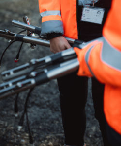
One of the great strengths of the In-Place Inclinometer is its continuous collection of measurements and real-time transmission (up to several measurements per hour with a static interrogation module, or even several measurements per minute with a dynamic interrogation module).
If inclinometric monitoring is to be proposed, the choice will be more towards In-Place inclinometer if the expected phenomena require near-real time monitoring, if the length of inclinometric tubes to be measured would be too time-consuming in terms of manual measurements, or if access to the tubes is too delicate (co-activity, inaccessible tube head, etc). In other cases, the choice will be more towards a manual survey.
What type of measurement is obtained?
This type of device provides a uni-axial or bi-axial deformation depending on the type of sensor used. A uni-axial measurement allows a single deformation to be obtained along the axis of the expected deformations (typically towards the front of a retaining wall during an excavation operation). A bi-axial measurement is interesting in cases where the expected deformations are in the horizontal plane.
STRUCTURAL AND GEOTECHNICAL MONITORING
Managing the integrity of your construction sites and maintaining safety of surrounding infrastructures
Our solution allows you to optimise your construction processes by leveraging the full potential of the observational method.
In what form can the data be read?
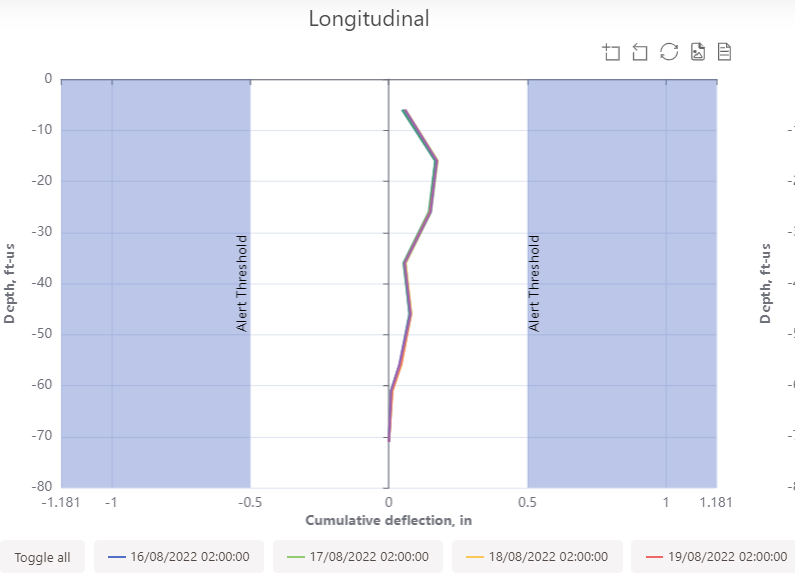
Use case example: Monitoring ground movement during tunnel boring
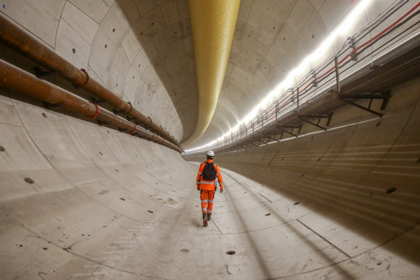
This device is regularly used to monitor impacts during tunneling. In the case of reinforced measurement sections requiring an increase in the number of measurements (sensitive surroundings in the area, area of geotechnical In the case of reinforced measurement sections requiring a higher number of measurements (sensitive neighbours in the area, geotechnical interest, cadence, or other), it is often requested to deploy inclinometric measurements to measure the earth pressure of a TBM during its passage. These measurements can be used to monitor the deformation of the ground during the passage of the active zone, to monitor the deformation of the ground around the deep foundations of sensitive existing buildings or to correlate the measurements with the soil surveys previously carried out.
The use of inclinometric measurements can also be used to determine the ovality of the retaining walls when the TBM arrives in a centred structure, when a tunnel connection branch is excavated in a non-centred structure, and/or to monitor the impact of the arrival of the excavation face on the deformation of a spandrel. This monitoring should be coupled with topographic measurements wherever possible for greater redundancy (inclinometer tubes that may be lost because they are blocked or bent, topographic targets that are subject to dirt, degradation, delicate topographic sights).
GOOD TO KNOW
In-Place Inclinometers can be installed from the natural ground, or in retaining walls or piles.
In the first case, the driller is usually responsible for installing the pipe during drilling. In weak ground, a temporary casing may be necessary.
In the second case, the installation of a reservation tube is essential during the installation of the reinforcement cages to facilitate the drilling operations. The driller can then lower his drill string to the bottom of the casing, drill a hole in the bottom of the wall (to guarantee anchoring in a stable zone), and install the inclinometer tube before sealing.
[FR] Rapport bibliographique : Observation des glissements de terrain – Nouvelles technologies d’instrumentation in-situ, Mars 2015, CEREMA
[FR] Méthodes d’auscultation de la structure, Auscultation des fondations, Les collections de l’IFSTTAR, Octobre 20215


